The long-term goal for NCSIDO is to create a multi-channel Software Defined Radio capable of simultaneously observing several frequencies and transmitters. However, it is important to start acquiring as quickly as possible so that experience can be gained in studying the actual data.
A Quadrature Demodulator (QD) is a piece of hardware that can be very useful for SDR practitioners interested in the receiving side of the process. A QD consists of a bit of circuitry which shifts the frequency of a signal or a group of signals down to baseband (zero or near zero frequency) while preserving amplitude, phase, and relative frequency information about the signal(s). It is especially useful for capturing radio frequency (RF) signals using analog input boards or sound "cards". Since there is only a limited frequency range that these boards are capable of capturing or digitizing, for example from zero to 20kHz or zero to 200kHz depending on the board, it isn't possible to capture a US FM Broadcast Band (88-108MHz) signal directly. A Quadrature Demodulator can be used to shift a selected signal, for example, KCSU at 90.50+/-0.05MHz down to 0.00+/-0.05MHz where any old analog input board or a high-end sound card can digitize this baseband signal and make if available for signal processing.
A brief(!) digression:
- If you're not very familiar with radio engineering or signal processing then you might be wondering about the reference made above to "negative frequencies", as in "0.00+/-0.05MHz". First of all, negative frequencies *do* exist although they aren't obvious or directly observable with our human senses. Their existence is well established by the mathematical methods used to describe signals especially those of complex algebra and trigonometry. As identified in the above example, KCSU's broadcast signal occupies a piece of the frequency spectrum which ranges from 90.45MHz to 90.55MHz which is used to carry the modulating information offered by this official radio station of Colorado State University. If somehow these signals were to be shifted down in frequency by 90.45MHz then they would occupy the piece of the frequency spectrum from 0.0MHz to 0.1MHz or 0-100kHz. No negative frequencies here - these signals could be captured by a single channel of an analog input board operating at 200kSample/second (Nyquist sampling theorum but that's yet another aside).
- Now if these signals were to be shifted down by 90.50MHz (their central or "carrier" frequency) then they would occupy a piece of the frequency spectrum from -50kHz to +50kHz, as mentioned above. In this case, a single channel of an analog input board (now operating at only 100kSample/second) would capture the entire group of signals but could not distinguish between the positive and negative frequencies and would superimpose them on top of each other (also known as "folding the spectrum") resulting in overlap of the various signals and ambiguity in the true frequency of a particular signal. As it turns out, the signals with negative frequencies are different from those with positive signals and carry this information with them, it is just that a single analog input channel is incapable of distinguishing them. A crude analogy would be the difference between color and black-and-white photography - one knows that the objects represented in a black-and-white photograph do possess individual colors but those colors are missing (to a certain degree) in the black-and-white representation. The luminance (or brightness) information of the original objects is what is predominantly contained in the black-and-white photograph.
- Continuing the analogy, it is possible to capture the color information of the objects if several black-and-white photographs are taken of them under subtly different conditions, that is, through different color filters. It is then possible to to combine these several black-and-white photographs using suitable mathematical techniques into a so-called "color" photograph which represents both the luminance and the chroma (color and saturation) information.
- The positive and negative frequency information of signals can be said to be contained in the phase information of these signals and this phase information can be experimentally obtained by simultaneously capturing the signals under subtly different conditions, that is using two analog input channels each operating at a different phase. This is where the "quadrature" in the name arises: the two analog input channels are operated with a 90 degree phase difference between them. This is termed "in quadrature". By using suitable mathematical techniques these two signals can be combined then positive and negative frequencies can be distinguished in the internal representation.
- There are many other interesting and important theoretical aspects of quadrature demodulation and significant practical aspects also. This (not so brief) digression is meant only to introduce this rich field.
- BTW, other names by which the QD is sometimes known as include: "quadrature downconvertor", "complex frequency convertor", "quadrature baseband detector", and various combinations of the same.
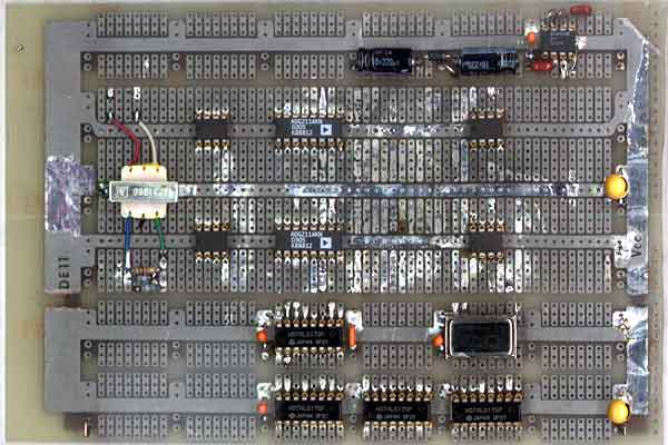
 I've built a QD for use in a ionospheric-monitoring, VLF radio [1] operating in the range 16-64kHz and interfacing to GNURadio with a standard (dual channel, <=48kSample/second, PCI) sound card. It uses a crystal-controlled 40kHz Local Oscillator, a pair of commutating-switch-style mixers, and differential signal paths. It was built to fit inside a typical PC tower, use the standard +5V and +12V DC power, offer an external input connector, and connect to the auxilliary input connector of the sound card. The board itself can be seen in the following image:
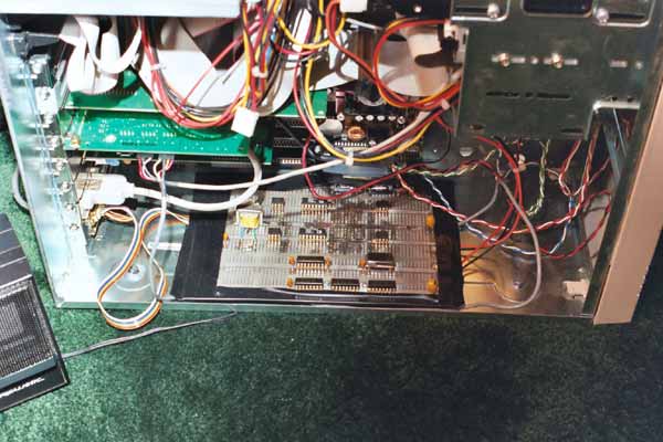
The board mounted inside a PC can be seen in the image at the left. The outputs of the board are routed to the internal inputs of a standard, "no-frills", PCI, sound card. The signals emitted by the QD board are of sufficient amplitude that they are relatively immune to the hostile EMI environment inside the PC.
The block diagram of the circuitry is shown in the figure below.
The various subsystems are described in detail below.
Input Buffer
 The Input Buffer serves to interface the D to the outside world safely and effectively. It uses a low-impedance, transformer-coupled input which effectively terminates standard Category 3 (two #24 wire twisted pairs) at VLF. The high impedance output of the transformer is terminated with a 1kOhm resistor and shunted with a pair of back-to-back 10V Zener diodes. These diodes limit any voltage which appears at the transformer output and protects the remaining circuitry. A pair of [Analog Devices] instrumentation op-amps [AD620] provides a differential, low impedance output for delivery to the following mixers. No external gain select resistors are used resulting in a voltage gain of one for this stage.
Mixers
The mixers used here combine the incoming RF signals with a local fixed signal (the Local Oscillator or LO) in a fashion which results in two output signals, occurring at the sum and difference of the signal's frequency and the LO's frequency. The mixers effectively act as analog computers which multiply the incoming signals to generate the outgoing ones.
 There are several types of mixers from which to choose in a particular design. The type used here is known as a commutating mixer or reversing-switch mixer. It utilizes several logic-controlled switches to route the incoming differential signals to the outgoing differential signals. Its operation can be understood by reference to a "crosspoint switch" represented in the following figure:
The logic signal is controlled by the LO which causes the mixer to alternately multiply the incoming RF signals by +1 and -1 at the LO's frequency. This multiplication provides for the mixing function. The actual switch used is an Analog Devices [ADG211A], a quad, SPST switch with logic control. Each of the two mixers is made up of four SPST switches in the following configuration:
In order for the switches to sequence properly two logic signals are required which are 180 degrees different in phase. These out-of-phase logic signals are provided by the LO.
The output impedance of the Mixer stage is effectively identical to the impedance of the Input Buffer stage which is the low output impedance of the instrumentation op-amp.
Low Pass Filter and Output Buffer
 The output of the Mixer stage is signals with the sum and difference of the RF and LO frequencies, however, only one is desired - the difference frequency which is in the baseband and capturable by the sound card. To eliminate the sum frequency signal a low pass (LP) filter is located at the output of each mixer, immediately preceding an output buffer amplifier consisting of another AD620 instrumentation op-amp. The LP filter is a simple, differential, single-pole, RC filter with a -3dB cutoff frequency of around 24kHz (which is the cutoff frequency of the sound card). The instrumentation op-amp offers a high-input impedance and does not load down the LP filter while providing a low impedance output suitable for driving a coaxial cable leading to the sound card input. Once again, a voltage gain of one is used for the output buffers.
A single-ended configuration was chosen for the QD output leading to the sound card to match the sound card's input. Additional instrumentation op-amps could be added if an analog input board with a differential input were used.
Local Oscillator
It is the job of the LO to provide two pairs of clean, stable, high drive level, differential signals in quadrature with each other. In this work four single ended signals were generated, providing each of four phases (0, 90, 180, and 270 degrees) which can be routed in two pairs. The LO's block diagram is shown below:
 A 3.840MHz, crystal-controlled TTL oscillator provides the necessary stability and accuracy. This TTL signal is routed through a series of dividers, made up of "walking-ring counters" to yield four phases of 40kHz. This divider chain is made up of four 74LS175 (quad, edge-clocked, D-type flip-flops). These parts were chosen because of their low power draw, high output drive, adequate frequency response, and because I have a bunch of them in my junk box. :)
Walking ring counters provide a convenient means for creating small integer dividers using only D-type flip-flops. They are extensively used and described. More information on these circuits can be found in Don Lancaster's TTL Cookbook ISBN 0672210355 (alternate, search) and CMOS Cookbook ISBN 0750699434 (alternate, search). The divide-by-6 and divide-by-4 circuits used in this work are shown here:
Note that two outputs are pulled from the divide-by-4 circuit to drive the subsequent four phase generator. Note also that using these circuits is very convenient and requires no extenal components - just wire up the ICs.
Four Phase Generator
 As mentioned above, four quadrature phases are required to drive the Mixer stages. A walking ring counter can be used to generate all four phase signals under two requirements:
- The clock which drives the counter must be at four times the desired LO frequency.
- Both the above mentioned clock must be supplied as must a second clock at the same frequency but 180 degrees out-of-phase.
It can be seen that the previously shown divide-by-4 circuit provides the two "anti-phase clock signals at the necessary 4xLO frequency. The circuit diagram of the four-phase generator is shown in the following figure:
The generator is made up of two separate 74LS175 ICs. The two lower flip-flops are configured as a divide-by-4 walking ring counter from which all four phases can be obtained. Unfortunately, because of internal IC designs and typical manufacturing tolerances which cause differential propagation delays it is possible that these four signals are not exactly in quadrature with each other. For this reason the second bank of (the top four) flip-flops are used to "resynchronize" the quadrature phases to the original 4xLO (160kHz) clock. The outputs of the resynchronizer flip-flops will only change on the rising edge of the 160kHz clock and their phase accuracy will be limited by its frequency accuracy.
Shake Down
The QD has been installed in a PC tower with a 266MHz AMD K6 CPU, 180MByte of RAM, a 9GByte and 0.5GByte disk pair, network card, and sound card. RedHat? Linux v8.0 is installed as is GnuRadio v0.8 and all the associated goodies. No monitor is attached to this computer and the xdm service has been activated to permit remote access to it using an xterm. Spiffy! A quick GnuRadio application was created to slurp data (and for me to learn how to do it) in from the sound card, apodize it with some reasonable windowing function, performa complex Fourier Transform, take the magnitude of the resulting frequency domain data, and display it. A screen dump of such a display follows:
The center of the display, labeled "0" actually corresponds to 40kHz because of the frequency shifting or translation process. The left and right ends of the display, labeled -24kHz and +24kHz, respectively, correspond to 16kHz and 64kHz, respectively for similar reasons. Several "live" radio station signals can be seen at around 25, 34, 36, and 60kHz.