One of the first questions we asked was how fast our projectiles were traveling. Answering that question is simple in theory but often more difficult in practice. First, let's cover the easy stuff.
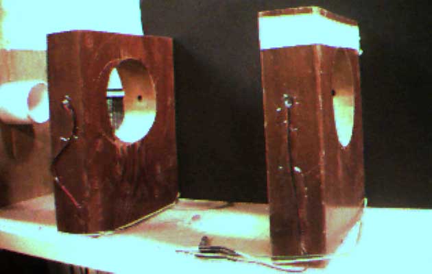 One of the more popular methods for measuring speed is to arrange for the object to pass through two separate beams of light a known distance apart along the path of travel and measure how long the time duration between breaking each of the two beams. The physical arrangement used can be seen in the image above. Two identical and substantial pieces of wood were drilled out to allow passage of the projectile and small (about 1/4" diameter) holes were drilled across the path. A super-bright visible LED was glued in each piece of wood and across from it a phototransistor was also glued. A phototransistor is definately favored for this application over a photoconductive cell because of its significantly faster transient response. Photoconductive cells can be made to respond more quickly but IMHO it's easier with a phototransistor. These two "timing stations" were then attached to the cradle with screws and glue. The path length was then carefully measured and found to be 19.8±0.1 cm.
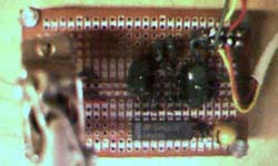 The eight leads from these pairs of light emitters and detectors were wired to a small circuit board also mounted to the cradle which held the electronics necessary to supply the proper bias to the LEDs and phototransistors and to condition the signals delivered by the phototransistors so they are suitable for accurate time measurement.
Anyone who has attempted to make a photodetector work properly in a real world application knows that it can be a real hassle. The simplest method is to include the photodetector in a voltage divider, create a second voltage divider with a variable resistor and use a comparator to indicate when the light at the photodetector changes by changing its output state. Unfortunately, this requires careful adjustment of the variable resistor to accomodate variations in ambient light conditions, temperature, accumulated dirt on the optical surfaces, etc. Multiple output transitions are not uncommon and can cause false triggering.
 The circuit shown in the figure below was first published in the CMOS Cookbook written by Don Lancaster, Howard W. Sams, Inc. 1977 and is billed as a "comparator circuit with a difference". It responds only to sudden changes due to the interruption of the light path and ignores slow changes in the light level and photodetector resistance. It also has the benefit of not requiring any critical adjustment to achieve this level of performance.
The main supply voltage is unipolar and can range anywhere from 5 to 20 volts with the LM324 quad op-amp used in our system. In normal operation, the voltage at point v must be set to somewhere between 0.5 to 0.9 times the supply voltage. A variable resistor can be used here for those who just have to have an adjustment but in our hands it was set once, a resistor was soldered in place, and it has never been changed since. In any event, the small-signal silicon diode across the comparator's inputs is forward biased by a small current flowing from point v, through the diode and through the high value resistor to ground. This ensures that the negative input of the comparator is maintained 0.6 V more positive than the positive input keeping the comparator's output low. The capacitor across the resistor to ground charges relatively quickly through the photodetector voltage divider but discharges relatively slowly through the resistor to ground.
When the light beam is suddenly broken, the voltage a point v falls quickly, the diode becomes reverse biased, the negative input of the comparator drops below the positive input, and the comparator's output changes state to the positive rail. The positive voltage from the output is fed back to the positive comparator through a series resistor and capacitor. This ensures that the positive comparator input is forced positive for a period of time during which the output remains positive and further input events are ignored. The values shown in the figure provide a time-out period of around one second which works well for many applications. The last two op-amps in the LM324 were used to buffer both comparators' outputs and ensure a time-out period independent on output loading considerations. The buffered outputs are also adequate to drive both CMOS or TTL inputs.
The two signals were delivered to a surplus frequency counter configured as an interval timer. The counter measured the time between the positive edge of each of the two signals which is equal to the time necessary for a projectile to traverse the distance between the timing stations. The speed is obtained by division of the distance by time.
